
Chip Load Explained
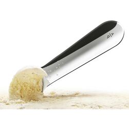
Do you like Ice Cream? If you do, you have probably had someone make you a cone and have seen "Chip Load" in action. Imagine two people, one small and one large, scooping your favorite flavor onto a cone. The smaller person, uses fast short shallow strokes producing small, thin slivers that has a tendency to melt as the ice cream is placed on top. The larger person, uses slow long deep strokes producing thick slivers that have a tendency to tip the bucket. This casual observation relates to "chip load " in the machining world as well in short,fast machining strokes, creating heat, and long, torque strokes creating stress. Both scenarios are not ideal to maximize tool/machine performance. A machines RPM and the FEED Rate have a direct relationship to each other and if you do not set the correct values, (the chip load) the result will be poor machine performance, parts moving, bit breakage. Short Strokes create "heat" resulting in shorter tool life, bit breakage. Long deep strokes="torque" result in bit breakage, poor edge quality and parts moving. Neither situation is ideal in the world of CNC machining. The right Chip Load measured in imperial or metric, explained further below, should be the perfect scoop of your favorite cone.

Chip Load in Perfect Balance
In simplest terms the equation to calculate Chip Load is Feed Rate in inches or millimeters divided by Number of Flutes multiplied by RPM illustrated by the equation above.
The relationship between Feed Rate, RPM and Number of Flutes have a direct or inverse relationship to each other. Increase/decrease either RPM or Feed, and the chip load will change, change both and the value can stay the same.
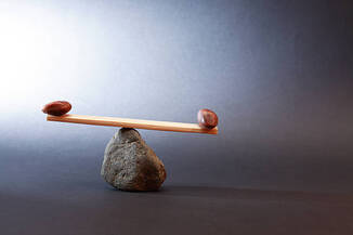
Like a See Saw, the goal of your CNC cutting strategy should be finding the perfect "balance" to your materials and surface finish. Adjusting the feed and or the RPM without the consideration of the counter effect is the reason most struggle with bit breakage and poor tool performance. Below is our downloadable help guide for materials in Wood and Plastic for chip loads.
The relationship between Feed Rate, RPM and Number of Flutes have a direct or inverse relationship to each other. Increase/decrease either RPM or Feed, and the chip load will change, change both and the value can stay the same.
Like a See Saw, the goal of your CNC cutting strategy should be finding the perfect "balance" to your materials and surface finish. Adjusting the feed and or the RPM without the consideration of the counter effect is the reason most struggle with bit breakage and poor tool performance. Below is our downloadable help guide for materials in Wood and Plastic for chip loads.
Click for: CNC CHIP Load Calculator
The more aggressive chip loads require the machine to exert more force on the material to cut it, and lighter chip loads require less force. The ideal chip load is a balance between tooling, machine power, and desired surface finish. It's important to note Chip load is directly correlated to tool wear. There’s an entire science to this, which is beyond the scope of this write-up. However, there’s a sweet spot for tool life longevity. A perfect balance!
The larger the chip, the more material the machine is removing at a time. The common oversight by CNC operators is that by increasing or decreasing one of the values above will not effect cutting performance without consequence. Because RPM and feed rate both affect chip load equally, you should keep in mind, changing only one of the values will have negative effects on your milling results and tool life, including good surface finishes and possible movement of parts.
If you’re experiencing lines, scalloping, or other short tool life issues it might be time to look at the strategy employed by your team of operators. The inventor of the strategy usually adjusts the chip load to give a “decent” result and the shortest reasonable milling times. There are usually gains to be made in quality and tool life if you’re willing to create standards for your machine and your processes.
- Be careful of speed or RPM adjustments on your machine