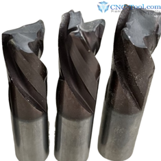
Causes for CNC Router Bit Breakage
Common Tool Breakage Issues
Common Tool Breakage Issues |
Recommended Remedy |
Incorrect Tool Holding System for the application |
Consider the right, appropriate, CNC Tool Holding Solution for your tolerance requirements. |
Deflection – Excessive Cutting-Edge Length |
Select a tool with a cutting edge length no more than 1/4” longer than the material thickness to minimize vibration and deflection. |
Excessive Tool Projection (Stick-Out) |
Keep the tool extension from the holder as short as possible to improve rigidity and reduce chatter. |
Worn or Damaged Collets |
. Inspect tool shanks for chatter marks or fretting. Replace worn collets regularly to maintain proper clamping force and concentricity. If tool slips, breaks, REPLACE the collet. |
Excessive Runout (T.I.R.) |
Improper spindle condition, damaged holders, or poor collet seating can create uneven flute loading and premature breakage. Verify runout periodically with a dial indicator. |
Improper Collet Torque |
Over- or under-tightening can damage the tool shank or allow tool slippage. Use a torque wrench and setup fixture to ensure proper tightening. (Torque Chart) |
Improper Chip Load |
Feed rates that are too slow may cause rubbing and overheating, while excessive feed rates overload the cutting edge. Improper chip load or surface footage (SFM) can cause premature tool wear, overheating, and eventual tool breakage. (chip load technical) |
Overheating |
Heat discoloration or buildup in the flute area may indicate poor chip evacuation or incorrect feed and speed settings. Inspect tools during and after production, evaluate the tool for discoloration, edge chipping and pitch build up. Adjust Chip loads. |
Part Movement or Poor Vacuum Hold-Down |
Insufficient workpiece hold-down can cause vibration, tool shock, and breakage. Improve vacuum performance or fixturing stability. Part movement adds stress and possible breakage. (holddown techniques) |
Excessive Pressure on Tool Tip |
In grooves, slots, and rebates, use the shortest cutting length and shortest overall length possible to reduce stress on the tool tip. Place as much of the shank into the tool holding system as possible. |
Tool Slippage in the Collet |
Replace static collet nuts with precision bearing nuts and inspect holder components regularly. (every 400 hours) |
Incorrect Tool Geometry |
Verify that the selected tool geometry is appropriate for the material and cutting application. (ie a 3-flute tool running at a 2-flute chip load) |
Material Contamination |
Staples, screws, dense glue lines, or foreign material may shock-load the cutting edge and cause sudden failure. Carbide/PCD will fracture hitting ferrous metals (nails etc) |
Tool Geometry Typical Application:
O-Flute Up Cut: Plastics, acrylic, aluminum
Double Edge O-Flutes:Developed for cutting harder plastics, such as acrylic and phenolics, at faster rates, smooth finish.
Low Helix: Hard Plastic, Soft Plastic, Solid Surface, Arcylic, and HDPE (Good universal plastic bit)
High Helix- Low density, foam, "closed" cell materials at high feed rates, open flute design "augers" out material.
Up Cut Spiral: Chip evacuation, dado cutting, nesting
Down Cut Spiral: Clean top-edge finish
Compression Spiral: Double-sided laminates and melamine
Mortise Compression: Improved finish in nested applications
Compression Chip Breaker: Reduced cutting pressure and improved chip control, furniture grade plywood best application.
Up Cut Chip Breaker: Aggressive material removal with reduced load
Down Cut Chip Breaker: Improved edge quality with reduced tear-out
Up Cut Rougher: Heavy stock removal
Down Cut Rougher: Reduced top-edge chipping during roughing
Ball Nose Up Cut: 3D carving and contour machining
Single Flute: Plastics and high chip load applications
Two Flute: General-purpose cutting
Three Flute: Higher feed rates and smoother finish quality
Best Practices to Maximize Tool Life
O-Flute Up Cut: Plastics, acrylic, aluminum
Double Edge O-Flutes:Developed for cutting harder plastics, such as acrylic and phenolics, at faster rates, smooth finish.
Low Helix: Hard Plastic, Soft Plastic, Solid Surface, Arcylic, and HDPE (Good universal plastic bit)
High Helix- Low density, foam, "closed" cell materials at high feed rates, open flute design "augers" out material.
Up Cut Spiral: Chip evacuation, dado cutting, nesting
Down Cut Spiral: Clean top-edge finish
Compression Spiral: Double-sided laminates and melamine
Mortise Compression: Improved finish in nested applications
Compression Chip Breaker: Reduced cutting pressure and improved chip control, furniture grade plywood best application.
Up Cut Chip Breaker: Aggressive material removal with reduced load
Down Cut Chip Breaker: Improved edge quality with reduced tear-out
Up Cut Rougher: Heavy stock removal
Down Cut Rougher: Reduced top-edge chipping during roughing
Ball Nose Up Cut: 3D carving and contour machining
Single Flute: Plastics and high chip load applications
Two Flute: General-purpose cutting
Three Flute: Higher feed rates and smoother finish quality
Best Practices to Maximize Tool Life
- Maintain clean spindle tapers and holders
- Replace collets regularly
- Verify spindle and holder runout periodically
- Use proper feed and speed calculations
- Minimize tool stick-out whenever possible
- Match tool geometry to the material being machined
- Ensure proper chip evacuation
- Use balanced holders for high RPM applications
- Inspect holders and tooling after crashes or heavy impacts