
CNC Fixture Part/s Hold Down White Paper
One of the challenges while operating a CNC machining center/router is the fixturing of the parts. The various methods of fixturing can often determine the result of the part quality and the machines performance. Several methods of part hold down fixture systems are available dependent on the industry.
The most common method in the WOOD,PLASTIC, COMPOSITE industries is the use of oil-less/dry, rotary claw pumps, as well as regenerative blowers configured for vacuum applications.
The most common method in the WOOD,PLASTIC, COMPOSITE industries is the use of oil-less/dry, rotary claw pumps, as well as regenerative blowers configured for vacuum applications.
1. Vacuum Fixture Hold Down Summary
The most common method in the WOOD,PLASTIC, COMPOSITE industries is the use of Vacuum/Blower fixture hold down. A vacuum table defined by Wiki:
"A vacuum table is a system for holding workpieces during machining. The device consists of a perforated table top containing a vacuum chamber, and a vacuum pump to keep the vacuum chamber below ambient enough pressure. The workpiece is placed on the top of the vacuum chamber and thus held down by the pressure differential between the vacuum chamber and the outside air." In vacuum hold down applications, the suction is created by using vacuum to move air in the opposite direction of the component being held in place. When air is removed beneath the part or component, the air above pushes down. The sucking of the air does not hold down the part. The atmospheric pressure above the part pushing down is what provides the hold down force and keeps the part or component in the correct place. Machines employing vacuum with full table and Rail/Pod(cup) hold down systems are typically with vacuum pumps. OEM's will size engineer the amount of vacuum based on the square inches of work surface engaged. Pumps range from 1-1/2 hp to 60hp. Factors to consider to ensure optimum hold down:
|
Below is a chart from OEM Becker Pumps highlighting relative vacuum to surface requirements. Generally speaking, when you want to match the right pump to the table size, you need 5.5 CFM per square foot of surface area for spoil board or nested base tables. Due to the small suction cups utilized by Pod and Rail tables, they require far less flow and typically use one size pump. (This sizing chart is for estimating purposes only, and you should consult a trained Becker Representative to match the correct pump to your specific table. All calculations are based on sea level applications.) Link to Becker Vacuum Pumps Guide to Vacuum
|

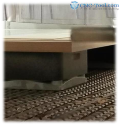
theWe will focus on Full Sheet Hold Down using full table NESTING CNC machines. Using a spoil board/slave board (Spoil Board best preparation guidelines), placed directly on top of the CNC work surface, the vacuum is drawn through the spoil board and holds the sheet of material.
HOW DO YOU KNOW YOU ARE GETTING THE BEST HOLD DOWN?
The answer is to create a standard (SOP) for your process, this starts with evaluating the performance of the vacuum to the table. The best way to determine the performance is to use the typically supplied pressure vacuum gauge installed on the machine. The gauge is the heartbeat of the vacuum's performance and provides real time feedback of the vacuum loss during machining operations. Gauges are unit of measure is typical Inches of Mecury (inHg) or Pascal (hPA). The challenge for most CNC operators is they do not recognize or understanding what the gauge represents and how to read it during daily operations.
Below is a guide to assist CNC operators with setting up a standard for their machines. What does the vacuum gauge indicate? We need to refer to the image on the left and the "baby on board" suction cup. In its simplest terms it is the purest form of a PERFECT vacuum. A smooth surface and no leaks! Now imagine a razor blade cutting one edge and allowing the smallest of leaks, and your ability to use your finger to lift the perfect seal away from the surface. The more cuts with the razor blade the greater the likely hood that the suction cup will no longer stay. With spoil board and sheet production, the same methodology is in effect. The gasket seal between the table and the spoil board and the seal between the material to the spoil requires the operators' attention to maintain the attempt at a perfect seal. Any loss in this standard will result in possible movement of parts.
The loss of air(CFM) created by the leaks is/has to be replaced by the pump and if the pump is not sized correctly to the table it more attention by the operator to the vacuum gauge will be required. Most CNC OEM mfg will typically engineer the machine's vacuum system with the correct pump size, table grid matrix, plenum chambers, multi-zones, and other solutions to maximize performance. Some CNC mfgs employ these methods, others do not. The most important thing for an operator is to create the "Standard" for you machine, your sea level, and the parts you plan to process. Help creating your standard is below.
Creating a Vacuum Hold Down Standard
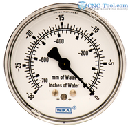
On the left is a vacuum gauge, installed on most CNC machines with a vacuum hold down system. The gauge is sometimes analog, like the picture and sometimes it's digital. The units of measure are inches of water or mm of water, Pascal or 1 bar (defined below) and has a maximum value at sea level of (29.92 inHG=1 Bar). The higher the elevation from sea level the less the vacuum. To create a standard, we must first create the optimum scenario, just like the baby on board sticker. The perfect vacuum seal starts with the PREPARATION of the vacuum system consisting of the CNC matrix table, the correct sealing "CNC Gasket" and the MDF Spoil Board.
CNC spoil Board application Instruction Guide and Practice-CLICK HERE
Once completed, an operator can evaluate his/her optimum machine pump performance, using the vacuum gauge to create a standard.
CNC spoil Board application Instruction Guide and Practice-CLICK HERE
Once completed, an operator can evaluate his/her optimum machine pump performance, using the vacuum gauge to create a standard.
- Confirm your pump is operating at its maximum performance, ie when pump is new, or new vanes, oil change, for its maximum pressure and CFM. (check with Pump/CNC OEM for additional information)
- Measure/record the vacuum gauge in inHG when vacuum valve is closed to the table to create your "pump ceiling standard".
- Prepare your spoil board/slave board with new gasket, sealing the edges as per suggested guide below and install a nonporous board on top of table. Remeasure your gauge in inHG to see the loss from your "pump ceiling standard" and record this value. This is your "production Ceiling Standard". Prepare spoil board: spoilboard_applications_tips_sb-2023.pdf/
- Continue with your production and continue to record the values in a chart to predict future changes.
- Test against other materials and create alternative charts.
- In wood nested mfg, typically its best to replace the spoil board/slave board once its reaches less than 3/8" or 10mm as the CFM to Pressure becomes unbalanced.
The typical loss experienced while operating, (in our experience) is around 4~6" inHG/ alternatively (101mmHG~152mmHG(0.135Bar~0.203Bar)
While operating the razor slicing/cutting process can create grooves in the spoil board table creating an uneven surface that breaks the perfect seal you started with for your "production ceiling" SOP. This process of "flycutting/resurfacing the spoil" is important to go back to the original "production ceiling". The operator will need to determine if the potential operating loss of 4-6 inHG while running will impact the parts machined. An important fact to remember is in most operations if your vacuum value is lower than 17" inHG (-431mm) your parts will begin to move. At 16" or lower, CNC mfg will typically E-Stop the machine to due safety concerns. If you continue to have parts that lose more vacuum/CFM than the pump can supply, the only option is to increase CFM to make up the loss. In certain applications a blower is required rather than vacuum.
On some CNC machines, in particular, the LCD pressure gage is a % of one Bar so range is equal to 29.92"=(1bar), 27"=(.914),24"=(.812),20"=(.617).18"=(.609),14"=(.474)
Vacuum Jigs - Dedicated Spoil Boards
On occasion a specialty or dedicated CNC Jig or vacuum fixture will be required to focus the vacuum to the individual parts and this can be accomplished using various CNC gaskets to create "on" board, or "in" board channels. Please contact us for further help in this use of specialty fixtures.
Mechanical Hold Down
Parts that are too small or have uneven surfaces, may require the use of mechanical clamping. Some of those methods or vises, pneumatic clamps @ 90~120psi, will grip the parts while allowing little to zero movement while under process. Some table systems that employ the use of mechanical clamp systems are considered to be Rail and Pod machines that have options to install these mechanical devices.
Blower Vacuum
For a lot of Porous applications including FOAM and the ratio of pressure to CFM requires further review and the side pressure of the manufacturing process is less while using a hot knife or reciprocation knife while using the CNC.
Some additional hold down methods that are common to the CNC industry include:
- Vacuum fixture hold down-utilizing vacuum pumps and or blowers.
- Pneumatic fixture hold down-piston cylinders with pneumatic pressure
- Hydraulic fixture hold down-piston cylinders with hydraulic pressure
- Magnetic fixture hold down-Magnets in the metal industry
- Manual Clamp Fixture hold down-bar clamp or mechanical vise with acme screw hold down